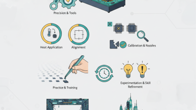
As electronic products become smaller and more powerful, dependable circuit-board repair is increasingly important. The World Semiconductor Trade Statistics (WSTS) forecast global semiconductor sales at approximately US$687.4 billion in 2025. That growth means more complex packages, tighter layouts, and greater pressure to recover expensive assemblies instead of scrapping them. A Bga Rework Station supports this need by removing and replacing Ball Grid Array components with controlled heat, alignment, and inspection.
Unlike leaded packages, BGA solder joints sit beneath the component body. They cannot be judged reliably by simple visual inspection. A professional station usually combines preheating, top-side heating, thermocouple feedback, adjustable airflow, and optical alignment. The operator first records the board condition, selects a compatible nozzle, and develops a thermal profile. The board may then be heated gradually, while the component reaches reflow temperature without overheating nearby parts. Small details matter. A warped board can cause open joints.
IPC-7095D provides design guidance for BGA technology, while IPC-A-610 defines widely used acceptance criteria for electronic assemblies. These documents support consistent decisions, but they do not eliminate process judgment. Moisture, oxidation, uneven heating, and operator technique can still affect results. A BGA rework station is not a magic fix. It is a precision tool within a controlled repair process. This article explains what the equipment does, how its heating and alignment systems work, and which practical checks help improve repeatability. Some repairs will still fail. Recognizing that limitation is part of reliable engineering.

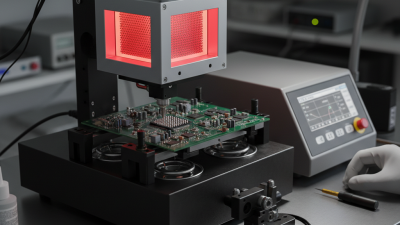
A BGA rework station is a specialized repair system for removing and replacing ball grid array components on circuit boards. Unlike a soldering iron, it heats the package and circuit board through controlled upper and lower sources. Its purpose is to restore boards when a BGA has solder defects, thermal damage, or requires replacement during testing. The station usually includes a heated work platform, adjustable nozzles, thermocouples, optical alignment, and programmable temperature control. These parts work together. They protect nearby components from unnecessary heat. A reliable operator also checks board thickness, component orientation, and moisture exposure before heating. Skipping these checks can turn a repair into permanent board damage.
During rework, the technician secures the board and aligns the replacement package with its solder pads. A controlled heating profile gradually raises the assembly through preheat, soak, reflow, and cooling stages. Thermocouples monitor actual temperatures near the joint, rather than relying only on the machine display. This distinction matters. Too little heat may leave open connections; too much can lift pads or warp the board. After cooling, inspection may use magnification, X-ray imaging, or electrical testing, depending on board complexity. From practical repair work, repeatability is often more valuable than speed. Still, no profile fits every board. Material changes, uneven copper layers, and operator alignment can affect results. A perfect-looking repair can still fail later if hidden joints were not properly verified.

A BGA rework station removes and replaces ball grid array packages without damaging nearby components or internal board layers. Its core function is controlled heat delivery. This matters as package density rises. The Semiconductor Industry Association reported global semiconductor sales of about $627.6 billion in 2024, increasing pressure to repair expensive assemblies rather than discard them.
The upper heater directs hot air or infrared energy onto the BGA package. A lower preheater warms the circuit board from underneath. This reduces thermal shock and limits board warpage. A nozzle concentrates airflow around the package. The nozzle size should match the component footprint, not the operator’s convenience. Optical alignment systems help center solder balls over the pads. Even a small offset can create open joints or bridging.
Thermocouples measure real board temperatures near the package. The controller then follows a programmed thermal profile, including ramp, soak, reflow, and cooling stages. IPC and JEDEC process guidance stresses controlled temperature exposure and moisture handling. Moisture-sensitive packages may require baking before rework. Nitrogen can reduce oxidation, though it is not automatically necessary for every repair.
Experienced technicians also inspect solder joints with X-ray or high-magnification optics. A shiny surface proves little. The 2024 electronics manufacturing outlook from IPC continues to identify skilled labor and process consistency as operational concerns. That reflects workshop reality: a sophisticated station cannot correct poor profile setup. I still find manual placement tempting during urgent repairs, but repeatability usually suffers. Calibration records, fixture stability, and operator judgment remain equally important.
A BGA rework station repairs a ball grid array package by controlling heat, airflow, alignment, and timing. Its operation requires more than simply heating a circuit board. The technician studies the board layout, identifies the component, and checks nearby parts for heat sensitivity. Board damage often begins with poor preparation.
The process starts with cleaning the work area and securing the PCB on a stable fixture. A preheating plate gradually warms the board, reducing thermal shock. The upper heater then follows a measured temperature profile, usually involving soaking, reflow, and controlled cooling. Thermocouples placed near the BGA help confirm the actual board temperature. The display alone is not enough.
When the solder softens, a vacuum pickup tool lifts the component vertically. Excess force can tear copper pads. After removal, the technician cleans old solder from the site and inspects every pad under magnification. A replacement BGA is aligned with optical guidance, then lowered carefully onto fresh solder. The station repeats the heating profile until the solder joints reflow evenly. Cooling must remain controlled.
Small errors matter. A slightly incorrect profile can create hidden voids, warping, or weak joints. In practice, operators sometimes adjust settings after reviewing inspection results, because one profile rarely suits every board. X-ray inspection provides stronger evidence than visual checking, though it also requires skilled interpretation. Mistakes happen. Good rework depends on measurement, patience, and a willingness to question the first result.
| Step | Operation Stage | What the Station Does | Main Equipment or Control | Typical Process Data | Expected Result |
|---|---|---|---|---|---|
| 1 | Board Inspection and Preparation | The operator identifies the faulty BGA, checks the PCB for warpage or damage, and removes nearby parts that could be affected by heat. | Microscope, PCB fixture, thermal shielding, ESD protection | Board pre-cleaning; controlled, static-safe work area; stable PCB support | The board is secured and the work area is ready for thermal processing. |
| 2 | Profile Selection | A temperature profile is selected according to the solder alloy, package type, PCB construction, and component manufacturer requirements. | Programmable temperature controller and profile software | Lead-free solder commonly uses a peak near 235–250°C; exact values depend on the approved profile. | The heating cycle has defined ramp, soak, peak, and cooling stages. |
| 3 | PCB and Component Alignment | An optical system or camera aligns the replacement BGA with the PCB land pattern using fiducials, package edges, or alignment marks. | Split-view optics, camera, X-Y-θ alignment table | Alignment is checked in the horizontal axes and rotational orientation before placement. | The package is positioned directly over the intended solder-pad pattern. |
| 4 | Preheating | Bottom heaters raise the PCB temperature gradually, reducing thermal shock and limiting the temperature difference between the board surface and the BGA area. | Infrared, ceramic, or forced-air bottom heater; thermocouples | Ramp rates are commonly controlled around 0.5–1.5°C per second, depending on the profile and assembly. | The PCB reaches a controlled preheat condition with reduced risk of warpage or delamination. |
| 5 | Flux Application | A suitable amount of flux is applied to the exposed solder pads or the replacement package to promote wetting and reduce oxidation. | Flux dispenser, stencil, syringe, or controlled manual applicator | Flux type and quantity must match the solder process; excessive flux can cause residue or movement during reflow. | The solder joints can form more consistently during heating. |
| 6 | Component Placement | The placement head lowers the BGA package onto the prepared pads with controlled vertical force and accurate positional registration. | Vacuum pickup nozzle, placement head, force or height control | Placement force is kept low enough to avoid damaging solder balls, pads, or the package substrate. | The BGA is seated over the pad array and held in position for reflow. |
| 7 | Controlled Reflow | The top heater supplies localized heat while the bottom heater maintains board temperature. Solder balls melt and form connections between the package and PCB. | Top and bottom heaters, closed-loop temperature sensors, programmable controller | Lead-free solder liquidus is commonly about 217°C; time above liquidus is often approximately 45–90 seconds, subject to the approved profile. | Molten solder wets the pads and package balls, creating electrical and mechanical joints. |
| 8 | Controlled Cooling | Heating is reduced gradually or cooling air is introduced so the solder joints solidify without excessive thermal stress. | Cooling fan, controlled airflow, temperature sensors | A controlled cooling rate, often around 1–4°C per second, is used when compatible with the solder and component profile. | The solder joints solidify and the component becomes mechanically stable. |
| 9 | Post-Rework Inspection | The operator checks package position, visible soldering conditions, surrounding components, and possible flux residue. | Microscope, optical inspection, electrical test equipment | Inspection criteria include alignment, lifted corners, bridging indicators, board damage, and contamination. | The assembly is screened for obvious defects before functional verification. |
| 10 | Verification and Documentation | The repaired board is tested for electrical and functional performance, while the thermal profile and inspection results are recorded for process control. | Continuity tester, functional test system, profile logger, inspection records | Test methods depend on the circuit design and may include continuity, power-up, signal, and functional checks. | The repair is accepted, reworked again, or rejected based on documented results. |
Note: Actual temperature, heating time, cooling rate, flux quantity, and placement force must be established from the solder alloy, BGA package, PCB design, and approved process specifications.
What Is a BGA Rework Station and How Does It Work?
BGA removal begins with controlled heat, accurate alignment, and careful board support. A rework station uses a heated air nozzle, infrared source, or both. The technician sets a temperature profile for the solder alloy and circuit board. Thermocouples placed near the component monitor real board temperature. This matters because displayed settings can differ from surface readings. The operator gradually warms the board, then lifts the package with minimal force. Never pry a BGA from softened solder.
Inspection follows removal. The board area is cleaned with suitable flux remover and inspected under magnification. Technicians check for lifted pads, solder bridges, burnt laminate, and hidden contamination. X-ray inspection can reveal internal voids or damaged connections. Some defects remain difficult to judge visually. That is where experience helps, though judgment is not perfect.
Replacement requires fresh solder spheres or a prepared package, depending on the repair method. The pads receive controlled flux, and the component is aligned using its corner marks and placement grid. A programmed heating cycle allows solder to reflow evenly. The technician watches for package movement, then lets the board cool without disturbance. Final inspection may include microscope checks, electrical testing, and X-ray verification. A small alignment error can cause intermittent failure later. I still recheck placement after cooling, because a successful-looking joint is not always a reliable joint.
A BGA rework station uses controlled, localized heating to remove a soldered BGA package, inspect and clean the site, apply a replacement package, and reflow the solder. The waveform below shows a representative lead-free SAC reflow profile used during BGA replacement.
The profile reflects common lead-free reflow targets: gradual heating, a 150–200°C soak, a peak typically below 245°C, and controlled cooling. Actual settings must be verified against the component and PCB manufacturer specifications.
What Is a BGA Rework Station and How Does It Work?
Key Factors Affecting Rework Quality and Reliability
A BGA rework station removes and replaces ball grid array packages with controlled heat and alignment. It uses a heating system, placement head, nozzles, and temperature sensors. Preheating reduces thermal shock across the circuit board. The upper heater then melts the solder evenly. A stable temperature profile matters greatly. Too much heat can damage pads, layers, or nearby components. Too little heat may create weak joints.
Rework quality depends on board preparation and operator control. Moisture inside the board or package can cause blistering during heating. Old solder, oxidation, and uneven paste deposits also reduce joint reliability. I have found that accurate nozzle alignment prevents unnecessary heating around the repair area. Thermocouples should contact practical measurement points, not just the package surface. A profile that looks correct on screen may still produce poor results.
Inspection must continue after the component is placed. Optical checks can reveal shifting, lifted edges, or excess solder. X-ray inspection may expose hidden voids and incomplete connections. The board should also receive electrical and functional testing. Cleaning is sometimes overlooked, especially around dense components. That is a mistake. Even experienced technicians may adjust heat too aggressively when a repair fails. Careful records, gradual profile changes, and honest review of each result improve repeatability. Perfect rework is difficult. Consistent control is the realistic target.