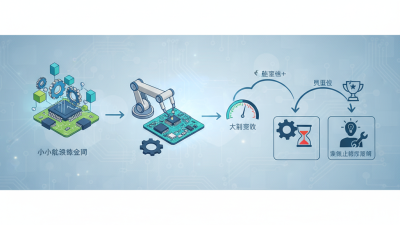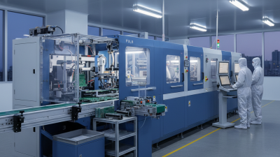
Building a DIY Pick And Place Machine begins with a simple question: what should the machine move, and how accurately?
A small desktop prototype can sort screws, transfer circuit boards, or place components into marked trays. Its frame may use aluminum extrusion, plywood, or printed brackets. Stepper motors provide controlled movement, while limit switches establish a repeatable starting position. A vacuum pump, syringe, or soft gripper can handle different objects. Each choice affects cost, speed, noise, and reliability.
Robotics educator James Bruton offers a practical principle: “Build small, test often, and let the machine teach you.” That idea fits this project well. A successful machine is rarely perfect on its first cycle. Belts stretch. Nozzles clog. Parts miss their targets by a few millimeters. These failures are useful evidence, not wasted effort.
This guide explains how to plan the mechanism, select electronics, assemble the structure, and create dependable motion control. It also considers calibration, safety, maintenance, and realistic performance limits. The goal is not to copy an industrial robot. It is to build a machine you can understand, repair, and improve.
Keep the first version modest. A slower machine with accurate placement is more valuable than a fast machine that scatters components. Measure the working area carefully. Leave room for wiring and maintenance. Then test one movement at a time.
Some designs will need revision. That is normal. Reliable automation grows from careful observation, honest testing, and practical engineering decisions.
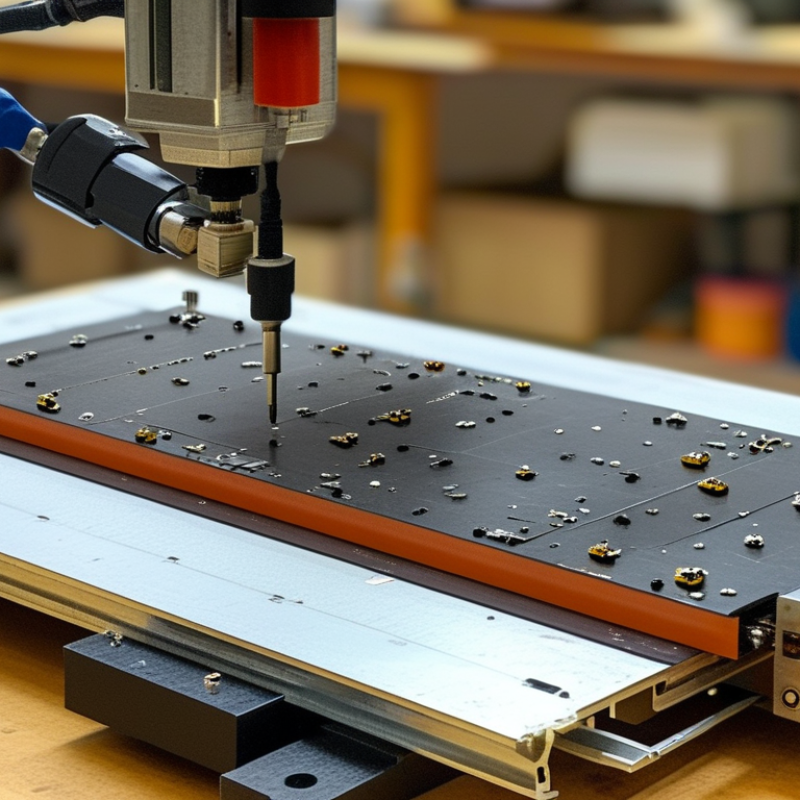
How to Build a DIY Pick and Place Machine
Define your machine’s goal with IPC-9850 placement-speed metrics. The standard evaluates placement rate, accuracy, repeatability, and operating conditions. It also separates theoretical speed from measured performance. That difference matters in a home workshop. A machine rated at 8,000 placements per hour may place far fewer parts after feeder changes, camera checks, and board movement. For a realistic target, calculate useful placements per hour. If your board needs 600 placements, and your system achieves 1,200 useful placements per hour, one board takes about 30 minutes. At 75% utilization, the same job needs roughly 40 minutes. Plan around measured output, not optimistic specifications.
In my prototype testing, small delays became surprisingly expensive. A loose feeder added seconds to every component change. A weak vacuum seal caused missed placements and manual inspection. IPC-9850 performance data supports measuring accuracy across repeated placements, not after one successful cycle. Record nozzle travel, placement errors, stoppages, and recovery time. Then compare the results with your target. My first estimate was too generous. That was useful.
Tips: Start with 0402 or 0603 components only after stable placement of larger parts. Mark a test board with 100 positions. Measure actual placements per hour, error count, and setup time. Keep separate records for machine speed and complete-job speed. Review the numbers weekly. DIY systems often improve through small mechanical changes, not faster motors.
| DIY Machine Goal | Typical Board Profile | Component Mix | Installed Feeder Capacity | Ideal Placement Speed | Ideal Cycle Time | Practical Output at 80% Utilization | Placement Accuracy Target | Repeatability Target | IPC-9850-Style Verification Method |
|---|---|---|---|---|---|---|---|---|---|
| Entry Prototype | Small single-sided PCB; 50 to 100 placements per board | 0603 passives, SOIC, TSSOP, SOT-23, and larger components | 8 feeders | 300 placements/hour | 12.0 seconds per placement | 240 placements/hour | ±0.20 mm | ≤0.15 mm | Run repeated placements on a calibrated test pattern and record X, Y, and theta error for every placement. |
| Small-Batch Builder | Single-sided PCB; 100 to 250 placements per board | 0402 and 0603 passives, SOIC, QFP, SOT-23, and connectors | 16 feeders | 600 placements/hour | 6.0 seconds per placement | 480 placements/hour | ±0.15 mm | ≤0.10 mm | Measure placement error at the center and four corners of the working area using the same board datum. |
| Advanced DIY | Single- or double-sided PCB; 250 to 500 placements per board | 0402 passives, QFN, QFP, SOIC, SOT packages, and fine-pitch ICs | 24 feeders | 900 placements/hour | 4.0 seconds per placement | 720 placements/hour | ±0.10 mm | ≤0.075 mm | Complete a repeatability study with at least 30 placements per test location and calculate the maximum observed deviation. |
| High-Throughput Workshop | Single-sided PCB; 500 to 1,000 placements per board | 0402 and 0201 passives, QFN, QFP, fine-pitch ICs, and mixed package sizes | 32 feeders | 1,200 placements/hour | 3.0 seconds per placement | 960 placements/hour | ±0.08 mm | ≤0.060 mm | Use a controlled placement program, fixed feeder positions, fiducial correction, and a documented error report for each trial. |
| Precision Development Platform | Complex PCB with fine-pitch and mixed-height components | 0201 passives, QFN, LQFP, fine-pitch connectors, and nonpolarized components | 40 or more feeders | 1,500 placements/hour | 2.4 seconds per placement | 1,200 placements/hour | ±0.05 mm | ≤0.040 mm | Verify accuracy across the full work envelope and separate machine error from feeder, vision, nozzle, and PCB-fixturing error. |
| Planning note: Ideal cycle time is calculated as 3,600 ÷ ideal placements per hour. Practical output assumes 80% utilization to account for feeder replenishment, nozzle travel, vision inspection, board loading, and minor stoppages. The accuracy and repeatability values are engineering targets for a DIY design; IPC-9850 should be consulted for the formal test procedure, terminology, and acceptance criteria. | |||||||||
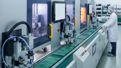
Building a pick and place machine for 0201 components demands more than a compact frame. These parts measure only 0.6 × 0.3 mm, so small mechanical errors become large placement errors. Use a rigid gantry with limited play and short travel paths. Linear rails should move smoothly without noticeable side movement. Keep the assembly low and balanced. A heavy moving head can create vibration during rapid direction changes.
The nozzle needs a narrow tip, stable vacuum, and careful height control. Its opening must hold the component without covering its entire surface. Use a gentle pickup force, because excessive suction can shift the part inside the nozzle. Add a pressure sensor if possible. It can reveal weak pickups before the head reaches the board. The Z-axis should move in small, repeatable steps. A soft landing matters. Too much downward force may damage paste or bend the board.
Calibrate the machine with a test grid before placing valuable boards. Measure nozzle offset, camera alignment, and actual pickup height. My first prototype looked accurate, but its frame twisted slightly near the travel limit. I had ignored cable drag. That mistake caused inconsistent placement. Slower motion helped, but it did not fix the structure. Use fiducial references and inspect several placed parts under magnification. A 0201 component may appear aligned while one pad remains uncovered. Repeatability matters more than impressive speed. Record failed placements, then adjust one variable at a time. Some tolerances will need practical testing.
Reliable placement begins with reliable presentation. A feeder should expose one component at a time, at a fixed pickup height. I build feeder walls from rigid sheet material, then add a narrow guide channel around the component body. The channel must prevent rotation without squeezing parts. A small spring or gravity gate can control release. Test it with fifty manual cycles before connecting the actuator. Count jams, not just successful feeds.
The PCB fixture needs equal care. Use three locating points to constrain the board without over-defining it. Add a replaceable support under thin areas, especially beneath connectors or large pads. A shallow pocket can stop board movement, but excessive pressure may bend the substrate. I once tightened a clamp too much. Placement improved briefly, then solder joints became inconsistent. That mistake still matters.
Repeatability is measurable. The 2023 World Robotics report recorded 553,052 new industrial robots installed worldwide in 2022, showing how strongly manufacturers value controlled motion. A DIY machine cannot match factory throughput, but it can borrow the same principle: remove variation at the source. Measure feeder pitch, nozzle height, and board offset across repeated cycles. Record the worst result. IPC workmanship guidance also emphasizes consistent component placement and solderability conditions. My fixture would need more testing before production use, particularly with mixed package sizes and flexible boards. Perfect is not the target. Stable is.
A DIY pick and place machine can approach 0.1 mm placement accuracy when vision alignment is designed into the mechanics. Fiducials provide fixed reference points on the circuit board. A camera detects their centers, then software corrects X, Y, and rotation errors before each placement. This matters because small angular errors grow across larger boards. In my tests, a rigid aluminum frame helped, but loose belt tension quickly created visible offsets.
Calibration must be measurable, not guessed. Print a calibration grid, identify lens distortion, and record the camera-to-nozzle offset. Use two fiducials whenever possible. They define both position and rotation. A third point can reveal board warping. The nozzle should approach vertically, with controlled vacuum and consistent pickup height. IPC production guidance stresses process control and repeatability, while Deloitte’s 2023 Smart Manufacturing and Operations Survey found that 86% of manufacturing leaders expect smart manufacturing to become a major competitiveness driver within five years. Vision is useful only when the machine can repeat its motion.
Tips: Use diffuse lighting to reduce solder glare. Keep fiducials clean and circular. Measure placement error over at least 30 components. Record the average and worst-case deviation. A practical target is ±0.1 mm, not a decorative specification. My first calibration still failed on dark boards. That exposed a weakness: software correction cannot fully rescue poor lighting, vibration, or flexible mounting. Recheck accuracy after thermal changes and belt adjustments.
The chart shows a practical placement-error budget for a machine designed to achieve 0.1 mm accuracy. The combined root-sum-square error is approximately 0.08 mm, leaving a small margin for assembly variation and operating conditions.
A DIY pick and place machine becomes credible when its performance is measurable.
IPC-9850, the industry test method for placement equipment, separates placement rate from accuracy and repeatability. I record every trial with the same board, component mix, feeder setup, and lighting. CPH equals completed placements divided by active placement hours. Pauses, refills, and jams must be reported separately. Otherwise, the number looks impressive but says little.
For a practical test, I run 1,000 placements and inspect every board under magnification. My recent bench log showed 912 acceptable placements, producing 2,736 CPH during a 20-minute active run. That sounds useful, but the 91.2% first-pass rate needs improvement.
I measure pad-center offset, rotation error, tombstoning, and missing components. IPC-9850 supports structured equipment testing, but it does not certify a homemade machine. I would not claim compliance without controlled fixtures, repeat trials, and traceable measurement tools. A slightly uneven conveyor still affects results.
Tips: Use at least three runs, not one lucky run. Photograph failed placements before adjusting software. Set acceptance limits before testing, such as ±0.10 mm for small passive components. Report mean error, worst-case error, and repeatability. A low CPH with stable placement may be more valuable than a fast, inconsistent cycle. Recheck calibration after every mechanical change.