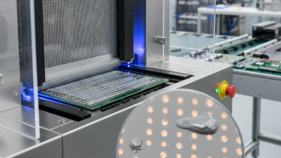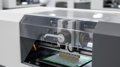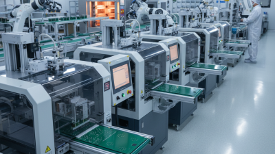
Choosing a Pcb Stencil Printer is not simply a matter of comparing speed, price, and brand reputation. In a real SMT line, paste release, alignment stability, cleaning access, and operator training affect every board. A printer may advertise 1,200 millimeters per hour, yet poor support for fine-pitch apertures can create hidden rework costs.
Industry data shows why this decision deserves careful attention. Grand View Research valued the global printed circuit board market at approximately USD 89.7 billion in 2023 and expects continued growth through 2030. More boards usually mean greater pressure on placement accuracy and process repeatability. IPC-7525B also emphasizes stencil design, aperture quality, and paste-control practices as important parts of printing performance. These references do not select a machine for you. They clarify what must be measured.
This guide presents seven practical tips for evaluating a Pcb Stencil Printer. The focus is concrete: alignment tolerance, frame compatibility, squeegee pressure, board support, cleaning cycles, software records, and after-sales service. Look closely at the first printed panel. Inspect fine-pitch pads under magnification. Check whether paste deposits remain consistent after several consecutive cycles. Small differences matter.
A perfect purchase is unlikely.
Manufacturers sometimes report ideal laboratory results. Production floors are less forgiving. Board warpage, changing solder pastes, humidity, and inexperienced operators can expose weaknesses quickly. The better question is not, “Which printer looks most advanced?” It is, “Which printer can deliver stable results in our actual process?” Reviewing supplier demonstrations, IPC guidance, and independent market research can support a more reliable decision. Still, your own trial data should have the final voice.
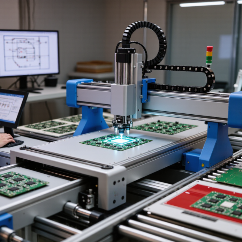
Choosing a PCB stencil printer starts with the production reality, not the machine brochure. Review board sizes, package density, changeover frequency, and monthly output. WSTS forecasts the global semiconductor market will reach about $697 billion in 2025, signaling continued pressure on assembly capacity. Yet demand is uneven across sectors. A printer optimized for high volume may waste time on short, mixed runs.
Tip 1: Map your board mix. Record the smallest apertures, largest panels, component pitches, and paste types. IPC-7525 recommends checking stencil aspect and area ratios, commonly using minimum targets of 1.5 and 0.66. These ratios help reduce incomplete paste release, especially around fine-pitch pads. Verify actual performance with your paste supplier. The printed result can still surprise you.
Tip 2: Match volume with process control. High-throughput lines need stable alignment, repeatable squeegee pressure, fast cleaning, and reliable recipe management. Low-to-medium volume shops may value flexible tooling and quick changeovers more than maximum board-per-hour ratings. IPC’s 2024 Electronics Industry Sentiment Report highlights continuing cost pressure and uneven demand across electronics manufacturing. That makes capacity planning less obvious. Ask for measured cycle times using your panel size, stencil thickness, and inspection criteria, rather than accepting headline specifications. Tip 3: Demand evidence. Review capability studies, paste-height data, and first-article results. A printer that handles one dense board well may struggle with a mixed portfolio. Calibration also needs a documented schedule. Perfect alignment on day one is not enough.
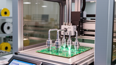
Choosing a PCB Stencil Printer: Set Alignment and Repeatability Targets Near ±25 µm for Fine-Pitch Printing
Fine-pitch printing demands more than a high-resolution specification sheet. Set alignment and repeatability targets near ±25 µm, especially for small apertures and dense component layouts. This tolerance should apply across repeated cycles, not only during one successful setup. Ask for measured data from production-like trials. A showroom sample proves very little.
During evaluation, print the same board several times after changing operators, shifts, and stencil positions. Measure pad deposits with calibrated inspection equipment. Check X, Y, and theta movement separately. Also examine paste volume, bridging, and aperture release. Small errors accumulate quickly. A printer may align well once, then drift after thermal changes or extended operation. I have seen clean first prints hide unstable results later.
Look for rigid tooling, controlled clamping, reliable fiducial recognition, and software that records correction values. The machine should maintain alignment after cleaning and stencil replacement. Request repeatability data at the intended board size and pitch. Generic figures can mislead. Keep the test environment realistic, including normal paste temperature and handling time. ±25 µm may be too generous for some advanced assemblies, while other boards may not need such precision. Define the target from actual pad geometry, process capability, and inspection evidence. Allow room for improvement.
A ±25 µm alignment and repeatability target represents an increasingly significant percentage of the available pitch as components become finer. For example, 25 µm equals 5% of a 0.50 mm pitch and 10% of a 0.25 mm pitch, making stable registration and repeatable printing essential for fine-pitch assemblies.
7 Tips for Choosing a PCB Stencil Printer?
When selecting a PCB stencil printer, match squeegee control to the stencil thickness. Common production stencils range from 50 to 150 µm. Thin stencils need gentle, stable pressure to avoid paste starvation. Thicker stencils may require higher force, but excessive pressure can damage apertures. Choose a printer with adjustable pressure, speed, and stroke length. Fine control matters.
Look for closed-loop pressure monitoring, not only a basic pressure dial. A stable reading helps maintain consistent deposits across large boards. Squeegee speed should remain steady from the leading edge to the trailing edge. Adjustable attack angle also helps when paste release changes between 50 and 150 µm. Test several settings using inspection data. Measure volume, height, and bridging after printing. Small changes can matter.
Keep the stencil support rigid and check alignment repeatability. A slight gap can create uneven paste transfer, especially with thin stencils. Use a compatible blade edge and replace it when wear becomes visible. I once blamed the printer for poor release, but the real issue was a tired squeegee. That mistake was useful. Ask suppliers for trial data using your actual board, paste, and stencil thickness. A printer that performs well at 100 µm may need different settings at 50 µm or 150 µm. Choose adjustable control over impressive specifications.
| Tip | Selection Dimension | Typical Requirement | Recommended Starting Specification | Why It Matters for 50–150 µm Stencils | Verification Method |
|---|---|---|---|---|---|
| 1 | Match pressure control to stencil thickness | 50–75 µm (2–3 mil) |
Programmable pressure with approximately 3–5 kg total force per 300 mm of squeegee length | Thin stencils can deform or deflect when excessive force is applied. Fine-pitch and micro-pad printing generally benefit from a controlled, low-force starting point. | Run a stepped-pressure trial and inspect paste deposits for smearing, skips, and insufficient transfer. |
| 2 | Use a wider pressure range for standard applications | 75–100 µm (3–4 mil) |
Programmable pressure with approximately 4–7 kg total force per 300 mm of squeegee length | This range covers many conventional SMT assemblies. The printer should maintain consistent force across the full print stroke rather than relying on a fixed spring setting. | Compare deposit volume across the front, center, and rear sections of the PCB using paste inspection or stencil-print measurement. |
| 3 | Allow higher-force capability for thick stencils | 100–150 µm (4–6 mil) |
Programmable pressure with approximately 6–10 kg total force per 300 mm of squeegee length | Thicker stencils and larger apertures may require additional force to maintain a clean paste roll and complete contact, especially with higher-viscosity solder paste. | Increase force gradually while checking for complete aperture filling, paste scooping, and excessive board or stencil deflection. |
| 4 | Prioritize constant squeegee speed | All listed thicknesses | Closed-loop speed control, typically adjustable from about 20–150 mm/s | Print speed influences paste rolling, filling, and release. Thin stencils often need a carefully tuned speed, while thick stencils may require a slower stroke for reliable aperture filling. | Record paste-transfer results at several speeds while keeping pressure, separation, and paste condition unchanged. |
| 5 | Check parallelism and squeegee compliance | Fine-pitch to large-aperture boards | Independent or mechanically balanced squeegee loading with adjustable blade angle, commonly around 60° | Uniform contact prevents one side of the stencil from receiving more force than the other. This is especially important when printing thin stencils, narrow apertures, or large PCB panels. | Use a parallelism check across the blade and inspect paste deposits at multiple locations on the panel. |
| 6 | Choose controlled stencil separation | 50–150 µm (2–6 mil) |
Programmable separation speed, commonly adjustable from approximately 0.1–5 mm/s | A controlled peel-off movement supports clean paste release. Faster separation may improve cycle time, but can increase defects on fine apertures or poorly releasing paste. | Optimize separation speed using printed-area-ratio data, then inspect for bridging, dog-ears, clogging, and incomplete release. |
| 7 | Confirm repeatability and recipe control | High-mix or production use | Digital recipe storage for pressure, speed, stroke, separation, snap-off, and cleaning settings | Repeatable recipes reduce operator-to-operator variation and make it easier to match squeegee settings to different stencil thicknesses and PCB designs. | Print the same board in repeated cycles and compare transfer efficiency, deposit height, area, and volume against defined process limits. |
A suitable stencil printer should support measurable inspection criteria, not only repeatable paste placement. IPC-A-610 provides visual acceptance guidance for soldered assemblies. It does not replace process control. Your engineering team should translate its requirements into SPI targets for solder volume, height, area, and offset.
Set those limits before comparing machines. Review the printer’s alignment accuracy, squeegee pressure control, print speed stability, stencil support, and cleaning performance. During trials, collect SPI data from fine-pitch pads, thermal pads, and large ground connections. These areas often reveal poor release or uneven pressure. Keep the board temperature and paste condition consistent.
Look for trends, not isolated results. A single acceptable print can hide gradual volume loss. Use control charts to identify drift and connect defects with printer settings. The acceptance window should reflect the assembly class, product risk, and customer requirements. Confirm the current IPC-A-610 revision and document who approves each limit.
A perfect print is unrealistic. Stable variation matters more. In practice, teams sometimes tighten SPI limits too early and create unnecessary alarms. That mistake can slow production without improving solder joints. We have found that a short validation run, followed by operator review, exposes weak criteria quickly. Ask the printer supplier for raw measurement access, repeatability data, and maintenance records. Reliable inspection begins with honest data.
Choosing a PCB stencil printer requires more than comparing advertised print speeds. In production audits, I compare completed panels per hour, not brochure cycle time. Throughput includes loading, alignment, printing, inspection handoff, and minor stoppages. A ten-second cycle may deliver fewer boards when operators wait for recipe confirmation. Measure several shifts. Track first-pass yield too. Fast is not always productive.
Changeover time often hides major labor costs. Record the time from the final accepted board to the first accepted board from the next job. Include stencil cleaning, paste setup, recipe verification, fiducial teaching, and squeegee changes. A fifteen-minute saving, repeated across frequent product changes, can recover hundreds of labor hours yearly. However, rushed changeovers can increase defects. I have seen teams trust one impressive demonstration. Use repeatability data from different operators and shifts.
Uptime needs evidence. Request maintenance records, mean time between failures, repair response times, spare-part availability, and software support terms. Calculate real availability from scheduled production hours, not ideal operating time. Five-year ownership cost should include installation, training, consumables, service, utilities, labor, downtime, and scrap. A lower-priced printer can cost more if it loses two production hours each month. Challenge every assumption. Energy estimates may be optimistic, and maintenance labor is easy to overlook. Use historical factory data wherever possible.