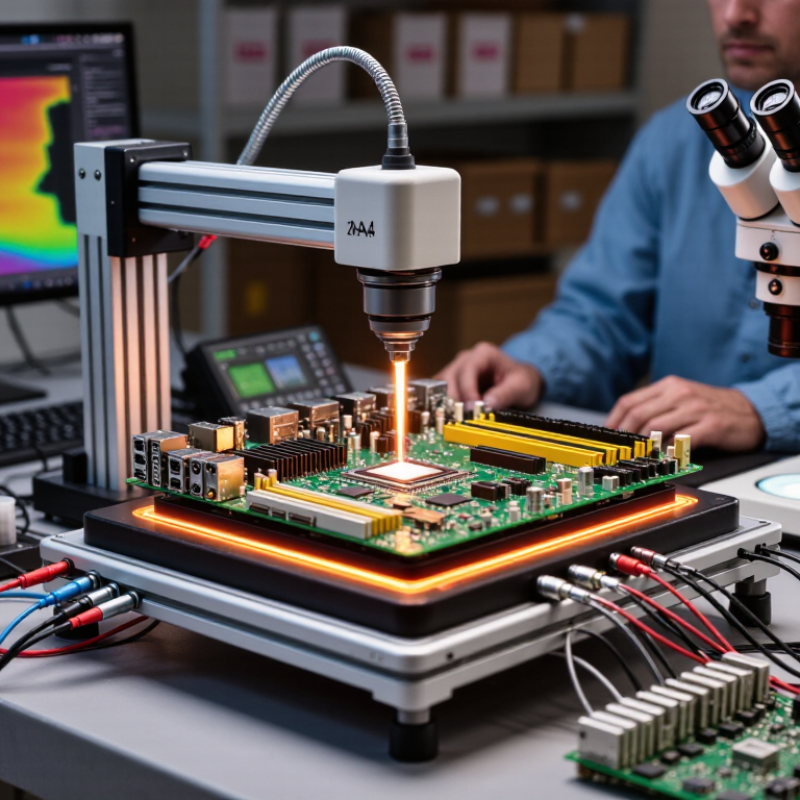
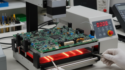
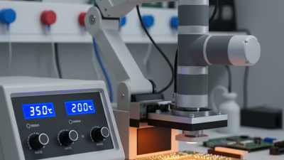
Repairing a dense PCB is rarely a matter of simply adding heat. Modern boards combine fine-pitch BGAs, multilayer construction, lead-free solder, and temperature-sensitive components. A Bga Rework Station provides controlled heating, accurate placement, and repeatable process management when manual methods become unreliable.
Bob Willis, a respected PCB assembly and rework specialist, has expressed the practical principle clearly: “Rework should be repeatable, measurable, and documented.” That principle explains why professional repair teams choose a dedicated Bga Rework Station. The equipment can preheat the board from below, protect nearby components, and apply localized hot air or infrared energy above the package. Operators can monitor thermocouples while following a defined temperature profile. The result is less guesswork around solder melting, component alignment, and pad protection.
Small errors matter.
A misplaced BGA may produce hidden bridges, opens, or damaged pads. Visual inspection alone cannot always reveal them. A controlled station, combined with X-ray inspection and skilled workmanship, improves confidence without promising perfection. Operators still need experience. Boards vary in copper density, moisture condition, package size, and thermal response. Even a sophisticated machine cannot correct a poor profile or careless handling.
Choosing a Bga Rework Station therefore means choosing process control, not just equipment. It supports traceable repairs, reduces unnecessary board replacement, and helps technicians repeat successful work. However, buyers should evaluate nozzle options, heating uniformity, software controls, calibration records, and operator training. The machine is valuable, but the process remains human.
At 0.4 mm pitch, BGA repair becomes a precision task, not a simple soldering job.
Ball spacing leaves little room for placement errors or uneven heating. IPC-7095C identifies fine-pitch BGA assembly as especially sensitive to warpage, solder bridging, and hidden joint defects. These faults remain invisible beneath the package.
A BGA rework station provides controlled preheating, focused hot-air delivery, and programmable temperature profiles.
The goal is to protect nearby components while melting the solder evenly. Thermocouples help verify board temperature, but measurement location matters. A sensor placed too far away can create false confidence. High-density boards also absorb heat differently across ground planes and copper layers.
WSTS forecast global semiconductor sales at 611.2 billion dollars for 2024, a 16 percent annual increase.
More complex devices support this growth, but they also raise repair demands. X-ray inspection, stencil control, and accurate nozzle alignment become increasingly valuable. IPC-7711/21 recommends documented rework procedures and process verification for reliable repairs.
Small mistakes matter.
A slight offset can damage pads or reduce joint reliability. The station is not a cure-all. Operators still need profile development, package inspection, and careful post-rework testing. That last step is often underestimated.
Why Choose a BGA Rework Station for PCB Repair?
Failure diagnosis should guide every BGA repair decision. A rework station provides controlled heating, accurate alignment, and repeatable temperature profiles. However, repair quality begins before the board reaches the machine.
X-ray inspection reveals hidden defects beneath the package. Look for missing balls, solder bridges, uneven collapse, voids, and possible head-in-pillow defects. Compare the image with the approved design and production records. IPC-A-610 provides visual acceptance criteria for electronic assemblies, but it does not replace process specifications. The required class and product conditions matter. A large void may look alarming, yet its acceptance depends on location, size, and applicable requirements. Do not judge from one image alone.
I have seen operators blame the rework profile too quickly. Sometimes the real cause is pad contamination, board warpage, or poor component placement. A second scan after rework can confirm whether the defect truly changed. Still, X-ray interpretation is not effortless. Image angle, magnification, and overlapping structures can mislead experienced technicians. Document the evidence, not just the decision.
Tips: Use the same inspection settings before and after repair. Record defect location, package reference, temperature profile, and operator observations. Verify acceptance against the correct IPC-A-610 class and customer criteria. If the evidence remains unclear, escalate the review rather than forcing a pass.
Failure Diagnosis: X-Ray Inspection and IPC-A-610 Acceptance Criteria
X-ray inspection is valuable for BGA defects hidden beneath the package, including open joints, missing solder balls, head-in-pillow indications, bridges, and solder-void distribution. A value of 1 indicates that the method can provide relevant evidence; 0 indicates that the method alone is insufficient. IPC-A-610 acceptance remains dependent on the applicable product class, defect definition, and current revision, so X-ray results should be combined with visual inspection and documented rework controls.
A BGA rework station offers controlled heat for repairs that ordinary soldering tools cannot manage. This matters when working with lead-free SAC alloys. Their reflow peaks commonly reach 235–245°C. Small deviations can change the result.
Thermal profiling should guide every repair. Technicians attach fine thermocouples near the BGA, on the board surface, and sometimes beneath the component. These readings reveal the actual temperature, not merely the station’s display. A controlled ramp reduces thermal shock. A stable soak activates flux and limits sudden expansion. The peak must melt the solder fully without overheating nearby connectors, laminates, or sensitive components.
Uniform heating is critical. A bottom heater supports the board, while the upper nozzle delivers focused energy. This arrangement reduces warpage and helps prevent uneven solder joints. I have found that air flow, nozzle distance, board thickness, and copper balance can shift the profile noticeably. One setting rarely fits every PCB.
Profile verification still requires judgment. A clean graph does not prove that hidden voids or pad damage are absent. Operators should inspect solder joints with suitable imaging and check electrical performance afterward. I once trusted a profile that looked acceptable, yet a dense ground area remained cooler than expected. That mistake showed the value of measuring difficult zones, not just convenient ones. Rework is controlled engineering, but it is never entirely automatic.
A BGA rework station gives PCB repair a controlled path from diagnosis to placement. The process begins with preheating, which reduces thermal shock and board warping. I usually secure the board, shield nearby parts, and attach a thermocouple near the BGA. A gradual profile matters more than raw temperature. The solder should soften evenly. During removal, the nozzle must match the package size. Stop there. If the chip resists, check the profile again. Pulling harder can lift pads or tear traces. After removal, I clean the site with suitable flux remover and inspect it under magnification. Small solder bridges are easy to miss.
Reballing requires a clean stencil, consistent paste, and steady alignment. The balls should sit in every opening. Uneven spheres often create open joints later. After heating the package, I check ball shape and spacing before placement. Good alignment matters. The package must match the land pattern without sliding across wet paste. A controlled reflow cycle lets surface tension center the device, but it cannot repair a badly prepared site. I have sometimes trusted a visual check too quickly. That mistake taught me to inspect edges, joints, and nearby components again. Electrical testing should follow cooling, not interrupt it. I record the profile and inspection results for the next repair.
| Step | Primary Objective | Typical Starting Parameters | Key Equipment Function | Critical Process Controls | Acceptance Indicators | Common Risks Without a Dedicated Station |
|---|---|---|---|---|---|---|
| 1. Inspection and Preparation | Confirm the defect, identify the package orientation, and protect nearby components before thermal work begins. |
Board temperature: 20–30°C before setup Recommended tools: microscope, board holder, thermocouples, flux, low-residue solder wick |
Provides stable PCB fixturing, controlled access, and accurate temperature monitoring. | Verify pad condition, component orientation, PCB layer sensitivity, and moisture concerns. Record the original defect and component location. | PCB is securely supported; pads are identifiable and free from loose contamination. | Board movement, incorrect orientation, lifted pads, and accidental damage to adjacent parts. |
| 2. Preheating | Reduce thermal shock and lower the amount of localized heat needed at the BGA package. |
Preheat zone: approximately 100–150°C Typical soak duration: 60–180 seconds Exact values depend on board mass, finish, and material |
Bottom or infrared preheaters warm the PCB evenly while the controller maintains a repeatable temperature profile. | Use at least one thermocouple near the BGA and another on the opposite side or nearby sensitive area. Avoid overheating connectors, plastics, and moisture-sensitive components. | Board temperature rises steadily with limited thermal gradient and no visible board discoloration. | PCB warpage, delamination, uneven solder melting, and excessive top-side heating. |
| 3. Controlled BGA Heating | Bring the solder joints to a consistent reflow condition without exceeding component or PCB limits. |
Lead-free peak: commonly about 230–250°C at the solder joint Leaded peak: commonly about 195–215°C at the solder joint Use the component and solder-paste specifications as the final authority |
Top and bottom heating zones create a controlled thermal profile instead of relying on a single hot-air stream. | Monitor ramp rate, soak period, peak temperature, and time above liquidus. Keep the nozzle centered and use the correct airflow for the package size. | Solder reaches a uniform molten condition and the component can be lifted with minimal force. | Uneven melting, solder splatter, neighboring component movement, and thermal damage. |
| 4. Component Removal | Remove the defective BGA while preserving the PCB pads and surrounding circuitry. |
Lift only after solder has fully reflowed Use vacuum pickup or a calibrated mechanical pickup Do not pry or twist the package |
Automatic or guided pickup helps maintain vertical movement and reduces mechanical stress on the board. | Confirm complete reflow through temperature readings and visual behavior. Apply only light vertical force and keep the package aligned with the nozzle. | Component separates cleanly; PCB pads remain attached and surrounding parts stay in position. | Pad cratering, pad lifting, board scratches, solder bridging, and damage to nearby components. |
| 5. Pad Cleaning and Inspection | Prepare a flat, clean, and solderable pad field for replacement or reballing. |
Use compatible flux and solder wick Inspect under magnification, typically 10× or higher Avoid excessive dwell time with the soldering iron |
Microscope access, stable fixturing, and controlled thermal tools improve pad-cleaning consistency. | Remove residual solder without scraping solder mask. Check for missing pads, exposed laminate, contamination, and solder-mask damage. | Pad field is level, clean, continuous, and free of solder bridges or loose debris. | Uneven joint height, insufficient wetting, open circuits, and permanent pad damage. |
| 6. Reballing | Restore the solder-ball array on a reusable BGA package when the package is otherwise suitable for reuse. |
Ball diameter must match the package design and process specification Use a matching stencil and compatible solder alloy Flux quantity: thin and uniform |
Reballing fixtures and controlled heating provide consistent ball placement and repeatable reflow. | Align the stencil with the package pads. Confirm every aperture is filled and remove excess flux before reflow. | All balls are present, centered, similar in size, and securely attached with no bridging. | Missing balls, offset balls, inconsistent joint height, shorts, and hidden opens after placement. |
| 7. Flux Application | Promote solder wetting and help the BGA self-align during placement and reflow. |
Apply a thin, even layer of flux Use a flux type compatible with the solder alloy, PCB finish, and cleaning process |
Controlled dispensing reduces excess residue and improves process repeatability. | Avoid flooding the site. Follow the flux manufacturer’s activation and cleaning requirements. | Flux covers the intended pad area without pooling or contaminating adjacent connectors. | Voids, residue-related leakage, solder bridges, poor wetting, and unreliable joints. |
| 8. Component Placement | Align the replacement or reballed BGA accurately with the PCB land pattern. |
Use optical alignment or precision camera guidance Confirm pin 1 and package orientation Placement force should be controlled and minimal |
Split-view optics, alignment cameras, and guided placement improve positional accuracy. | Match the package edges and fiducials. Check for solder-ball contact with all corresponding PCB pads before heating. | Package is centered, correctly oriented, and stable on the fluxed pad array. | Misalignment, rotated installation, solder shorts, open joints, and damaged solder balls. |
| 9. Reflow and Cooling | Form reliable solder joints and allow the assembly to cool without mechanical disturbance. |
Follow a measured profile for the selected solder alloy Use gradual cooling; avoid moving the PCB while joints are solidifying |
Closed-loop temperature control provides repeatable heating and controlled cooling. | Record the profile with thermocouples. Keep the board level and prevent vibration during solidification. | Reflow profile is within specification; no visible package shift, bridging, or abnormal residue is present. | Cold joints, excessive voiding, package warpage, solder bridging, and post-reflow displacement. |
| 10. Post-Rework Inspection and Testing | Verify mechanical placement, solder integrity, electrical function, and long-term reliability. |
Visual inspection: microscope or suitable optical system Electrical testing: continuity, resistance, functional test, or X-ray when hidden joints require evaluation |
Integrated inspection access and repeatable profile records support process verification and traceability. | Compare results with the original failure mode. Use X-ray or other non-destructive inspection when BGA joints cannot be evaluated visually. | Correct orientation, no visible defects, acceptable electrical performance, and documented process results. | Undetected opens or shorts, intermittent failures, repeat repairs, and incomplete quality records. |

A BGA rework station supports controlled PCB repair, but quality depends on verification, not heating alone.
J-STD-020 profiles provide the thermal baseline for moisture-sensitive packages. Operators should attach fine-gauge thermocouples near the package body and nearby board area. They must record ramp rate, peak temperature, and time above liquidus. Small errors matter.
IPC-7095 guidance treats voiding, head-in-pillow defects, and pad cratering as critical BGA risks.
X-ray inspection reveals hidden solder joints that optical inspection cannot reach. It can show void location, shape, and distribution. However, X-ray cannot prove metallurgical strength. That limitation deserves attention.
For uncertain repairs, cross-section sampling can confirm solder collapse and intermetallic formation. A practical station should preserve profile files, operator identity, board number, and inspection images.
Yield control turns repair activity into measurable process evidence.
Track first-pass yield, defect-per-million opportunities, rework rate, and defect Pareto charts by package type. The WSTS Spring 2024 forecast placed global semiconductor sales at 611 billion US dollars for 2024, a 16% annual increase. Higher production pressure makes repeatable rework more valuable.
IPC’s 2024 industry sentiment reporting also identifies quality and capacity as continuing operational concerns. Yet perfect yield claims can mislead. Recheck sampling plans, calibration intervals, and X-ray judgment regularly. A clean image is not always a reliable repair.