Reliable soldering is not achieved by heat alone. It depends on controlled heating, repeatable timing, and verified cooling. A Pcb Oven helps manufacturers create this stable thermal environment across every assembly. The result is more consistent solder joints, fewer cold connections, and better process control.
IPC-7530A, Guidelines for Temperature Profiling for Mass Soldering Processes, recommends profiling each assembly rather than trusting fixed oven settings. Board thickness, copper weight, component density, and solder paste chemistry all change heat transfer. A small connector may remain cool while a large ground plane absorbs energy. That difference can produce uneven reflow. Consistency matters.
IPC’s 2024 Global Sentiment of the Electronics Industry Report highlights continuing pressure to improve productivity, quality, and supply-chain resilience. These pressures make repeatable soldering increasingly valuable. A properly profiled Pcb Oven supports those goals by reducing manual variation and creating traceable process records. IPC-A-610 also provides widely used acceptance criteria for electronic assemblies, helping teams judge solder quality consistently.
The oven is not magic. Poor stencil printing, expired paste, or incorrect component placement can still create defects. That limitation deserves attention. Experienced engineers therefore combine thermal profiling, solder-paste inspection, and visual inspection. They may also use X-ray inspection for hidden joints and voids. The details matter.
When temperature curves are saved and reviewed, operators can identify drift before it becomes a batch problem. This practical discipline strengthens reliability, supports customer audits, and protects long-term product performance. A Pcb Oven is valuable because it turns a sensitive soldering stage into a measurable, repeatable manufacturing process.
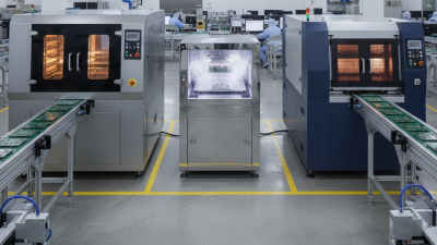
A PCB oven is a controlled thermal chamber designed to heat solder paste evenly across an assembled circuit board. Unlike a kitchen oven, it follows a programmed temperature profile. The process usually includes preheating, soaking, reflow, and cooling. During reflow, solder particles melt and form electrical and mechanical joints. Fans circulate heated air, while sensors monitor temperatures at several points on the board.
A practical profile matters more than a high maximum temperature. Operators attach thermocouples near large connectors, fine-pitch parts, and the board edge. These areas heat differently. A stable profile can reduce cold joints, solder bridges, and component stress. The 2024 IPC International Technology Roadmap identifies finer features and higher component density as continuing production challenges. That makes controlled heating increasingly important. Grand View Research estimated the global PCB market at approximately 81 billion US dollars in 2023, showing the scale of products relying on consistent board assembly.
Real boards are less obedient.
A profile that looks perfect on screen may still produce uneven joints. Board thickness, copper mass, paste condition, and loading patterns can change the result. I have found that filling every oven shelf can slow heating around heavy copper areas. That mistake is easy to miss. Recording temperature curves, checking paste storage, and inspecting joints under magnification provide stronger evidence than appearance alone. Small adjustments often improve yield more than simply raising the oven temperature.
A PCB oven earns its value through controlled heat, not simply high temperature. During reflow, each board should follow a defined thermal profile. The IPC-7530C guideline commonly supports ramp rates near 0.5–1°C per second. For lead-free solder, many production profiles target 217°C or higher for about 60–150 seconds. Peak temperatures often remain near 235–245°C, depending on the paste and components.
Modern PCB ovens divide the heating tunnel into zones. Each zone adjusts power, airflow, and temperature separately. Preheat zones remove moisture and reduce thermal shock. Soak zones stabilize the board before melting begins. Reflow zones deliver controlled energy around the solder’s liquidus temperature. Cooling zones then reduce temperature gradually. According to IPC-7530C, profiling should use thermocouples attached to representative components, pads, and board areas. A surface sensor alone can miss a cooler connector or a hotter copper region.
Technicians should verify profiles with actual production boards. Board thickness, copper weight, and component density change heat absorption. Conveyor speed matters too. A small speed error can shift time above liquidus by several seconds. Still, no profile is perfect. One test board may hide variation across a full panel. This is where oven logs, regular calibration, and repeated measurements improve reliability. The NIST Temperature and Humidity Measurement Guidelines also stress traceable measurement practices. That detail is easy to overlook. It should not be.
A PCB oven improves soldering reliability by controlling reflow conditions with precision. In practical assembly work, stable heat helps solder paste melt evenly across the board. The oven follows a planned profile: preheating, soaking, reflow, and cooling. Each stage affects the final joint. A temperature rise that is too fast can damage components or trap flux. A slow rise may cause uneven activation. Small variations matter.
Controlled reflow improves solder joint reliability through consistent wetting and cooling. Properly melted solder forms smooth fillets around component leads and pads. This reduces weak connections, voids, and uneven surfaces. A thermocouple attached near critical components can reveal the board’s real temperature. The oven display alone is not enough. Different board thicknesses, copper areas, and component sizes require profile adjustments. Heavy copper zones often heat more slowly.
Controlled equipment is not magic. I have seen good profiles fail because of oxidized pads, excessive paste, or warped boards. A perfect temperature curve can still produce poor joints. Inspection under magnification should follow every profile change. Sometimes the recommended settings need careful adjustment. That part is easy to underestimate. Recording defects beside temperature data helps connect visible failures with process conditions. Even experienced technicians can miss a small cold joint during a rushed inspection.
Controlled reflow improves solder joint reliability by maintaining a repeatable temperature profile across the entire PCB assembly.
The profile represents a typical lead-free SAC reflow target: gradual preheating, a controlled time above liquidus, a peak temperature near 245°C, and managed cooling. Consistent heating helps reduce cold joints, solder bridging, component damage, and thermal stress.
Typical process targets shown: ramp rate about 0.5–1.0°C/s, time above 217°C approximately 45–90 seconds, and peak temperature approximately 235–250°C. Final settings should follow the solder paste and component specifications.
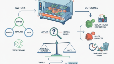
A PCB oven creates a controlled thermal profile, helping solder joints heat evenly and cool safely. Choosing the right model starts with your board size, component density, and daily production volume. Measure the largest assembly, including its carrier and clearance space. A compact oven may suit prototypes, but it can become a bottleneck during repeated production runs. A larger oven is not automatically better. Excess capacity can increase energy use and make temperature control less efficient.
Profile accuracy matters more than impressive temperature ranges. Look for several heating zones, stable airflow, recipe storage, and clear data logging. These features help operators repeat a proven process instead of guessing each time. Confirm that the oven supports your solder alloy and component limits. Ask about calibration, maintenance access, and recovery time after loading a cold board. In practice, neglected sensors can quietly damage process reliability.
Tips: Measure twice. Test with a loaded carrier, not an empty chamber. Use thermocouples on heavy copper areas, small components, and heat-sensitive parts. Compare the measured profile with the solder paste supplier’s recommendations. Leave room for future products, but do not pay for capacity your workflow cannot use. Review the first results honestly; an apparently stable profile may still hide uneven heating.
Why Use a PCB Oven for Reliable Soldering?
Best Practices for Safe and Effective PCB Oven Use
A PCB oven delivers repeatable heat, but only when the profile is measured. IPC/JEDEC J-STD-020 recommends controlled ramp rates, soak periods, peak temperatures, and time above liquidus. For many lead-free assemblies, peak temperature commonly reaches 235–250°C, with liquidus exposure near 45–90 seconds. These figures guide setup, not blind operation.
Measure the board, not only the oven air. Attach thermocouples near large copper areas, small components, and temperature-sensitive parts. Compare the recorded curve with the solder-paste supplier’s technical data. IPC-7530 recommends profiling production equipment because chamber displays can differ from board temperatures. That difference matters.
Safety starts before heating. Inspect cables, trays, and ventilation paths. Keep combustible materials away, and use temperature alarms and emergency shutdown controls. NFPA 86 provides safety guidance for industrial ovens, including ventilation and fire prevention. Operators should use suitable heat-resistant gloves and eye protection. Never open a hot chamber casually.
Keep records.
Log each profile, calibration date, paste lot, and unusual defect. Tombstoning, solder balls, or dull joints may indicate poor profiling, contamination, or placement stress. I have seen teams adjust peak temperature first, although airflow and ramp rate were the real problems. That shortcut deserves review. A successful profile is not permanent; board density, copper weight, and ambient conditions can change it.
| Process Dimension | Typical Data or Setting | Recommended Practice | Reliability Benefit | Verification Method |
|---|---|---|---|---|
| Solder Alloy | Lead-free SAC alloys commonly melt at approximately 217°C. | Confirm the alloy composition and liquidus temperature before programming the oven. | Prevents insufficient melting, excessive heating, and unreliable solder joints. | Check the solder paste technical data sheet and material lot information. |
| Ramp-Up Rate | Approximately 1–3°C per second | Use a controlled temperature increase rather than applying maximum heat immediately. | Reduces thermal shock, component cracking, solder splatter, and paste spattering. | Measure the board temperature with thermocouples during a profile run. |
| Preheat and Soak | Many lead-free profiles use approximately 150–200°C for 60–120 seconds. | Allow the board, components, and solder paste to heat evenly before reflow. | Improves flux activation and reduces temperature differences across the PCB. | Review the measured profile for stable heating and acceptable temperature spread. |
| Time Above Liquidus | Often approximately 45–90 seconds above 217°C for lead-free solder | Keep the time above liquidus within the solder paste and component specifications. | Provides adequate wetting while limiting intermetallic growth and component stress. | Use profile software to calculate the actual time above liquidus. |
| Peak Temperature | Typical lead-free peak values are commonly around 230–250°C, but package limits vary. | Set the peak temperature according to the most heat-sensitive component and the paste profile. | Reduces the risk of delamination, warpage, solder joint damage, and component failure. | Compare the measured peak with each component manufacturer’s rated reflow limit. |
| Cooling Rate | A controlled rate of approximately 2–4°C per second is commonly used. | Avoid sudden cooling unless the approved process profile specifically permits it. | Limits thermal stress and helps produce consistent solder joint microstructures. | Confirm the cooling slope using thermocouple profile data. |
| Temperature Uniformity | Maintain a small temperature difference across the populated board; many processes target no more than approximately 10°C variation near peak. | Place thermocouples at large copper areas, corners, small components, and heat-sensitive parts. | Reduces cold joints, overheated components, solder bridging, and uneven wetting. | Run a loaded-board temperature profile rather than relying only on the oven display. |
| Oven Calibration | Temperature sensors and control systems should be checked at defined maintenance intervals. | Use calibrated measurement equipment and document calibration results. | Improves repeatability between production runs and helps identify drift early. | Compare independent thermocouple readings with programmed zone temperatures. |
| PCB Loading | Board mass, copper distribution, panel size, and spacing affect heating behavior. | Keep board orientation, spacing, support, and loading quantity consistent. | Prevents profile changes caused by different thermal loads. | Reprofile the oven after changing board design, panelization, or loading conditions. |
| Moisture Control | Moisture-sensitive components may require dry storage and controlled floor life. | Follow the moisture sensitivity level and handling instructions marked on component packaging. | Reduces the risk of internal package cracking and “popcorn” damage during reflow. | Track exposure time, storage humidity, and required baking conditions. |
| Solder Paste Handling | Paste storage and working life depend on the material supplier’s specifications. | Use temperature-controlled storage, allow paste to reach room temperature as specified, and record opening time. | Maintains stencil print quality, flux performance, and solderability. | Check paste expiration date, viscosity condition, and print inspection results. |
| Ventilation | Flux vapors and heated residues can be released during reflow. | Use the oven’s exhaust system and provide adequate workplace ventilation. | Improves operator safety and reduces residue accumulation inside the oven. | Inspect exhaust flow, filters, ducts, and visible residue at scheduled intervals. |
| Fire and Electrical Safety | Reflow ovens operate at high temperatures and draw significant electrical power. | Use proper grounding, circuit protection, clearances, emergency shutdown access, and suitable fire-control equipment. | Reduces the risk of burns, electrical faults, smoke events, and equipment fires. | Perform documented safety inspections and follow the oven manufacturer’s operating instructions. |
| Inspection After Reflow | Common defects include tombstoning, bridging, insufficient wetting, voiding, and component movement. | Inspect solder joints using visual inspection and, where required, automated optical inspection or X-ray inspection. | Detects process defects before they become field failures. | Use applicable workmanship requirements such as IPC-A-610 and maintain defect records. |
| Profile Documentation | A complete record includes board identification, solder paste, oven settings, measured temperatures, and operator details. | Save an approved profile and repeat the measurement after significant process or material changes. | Supports traceability, process control, and repeatable production quality. | Review profile records, inspection results, and corrective-action history. |