inquiry
Leave Your Message

Top 10 Pick and Place PCB Machines for Buyers in 2026

Choosing a Pick And Place Pcb Machine in 2026 means matching production needs with practical machine capabilities. This guide introduces ten options for buyers comparing equipment for different board sizes, component types, and output targets. The right choice depends on more than placement speed. Feeder capacity, supported component ranges, setup time, software usability, and local service can shape everyday results.

A machine that looks impressive in a specification sheet may still create bottlenecks on your floor. Check whether its placement accuracy fits your components, and ask how changeovers work for short production runs. Consider the available space, operator training, maintenance access, and the cost of feeders or replacement parts. Small details matter. A compact machine may suit a limited workspace, while a higher-capacity model may better support frequent product changes. Neither is automatically the better investment.

This top 10 overview gives buyers a structured starting point, not a universal ranking. Compare each machine against your actual boards and workflow, and confirm specifications directly with the manufacturer or distributor. Ask for a demonstration using representative components when possible. Even a strong shortlist can miss your real production bottleneck. More features are not always better. A measured comparison of capability, support, and total ownership cost can help you choose equipment that fits today’s workload without overlooking future needs.
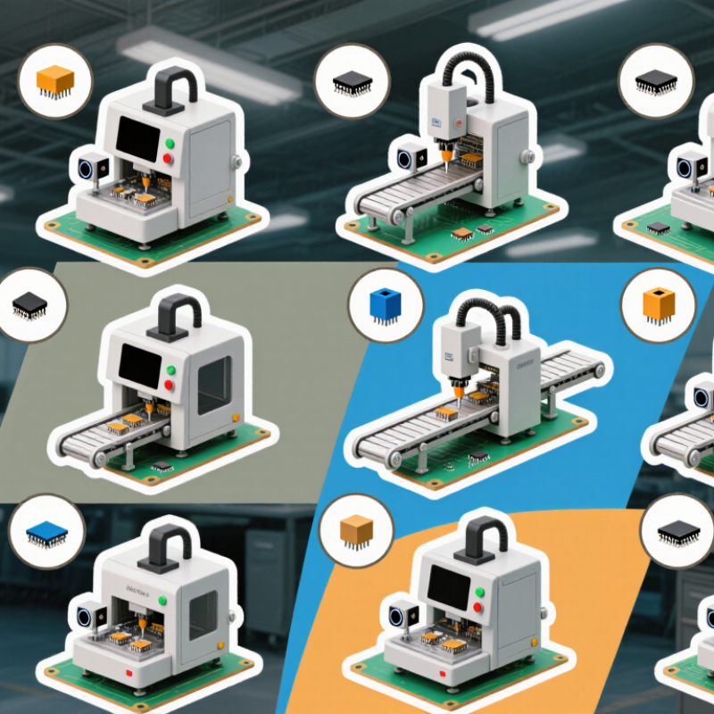
Top 10 Pick and Place PCB Machines for Buyers in 2026

How Pick-and-Place Machines Support PCB Assembly

Top 10 Pick and Place PCB Machines for Buyers in 2026

How Pick-and-Place Machines Support PCB Assembly

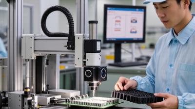
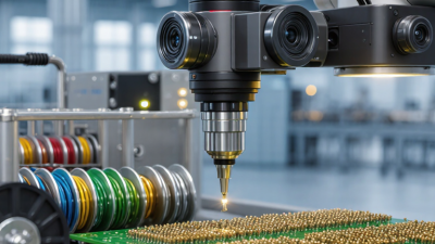
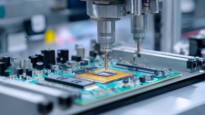
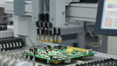
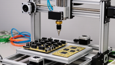
A pick-and-place machine moves electronic components from feeders onto solder-paste-coated circuit boards. Its camera checks component orientation and board position before placement. This helps align tiny parts, such as resistors, with their pads. The board then moves to a reflow oven, where heat forms solder joints. Precise placement matters. A shifted component can cause poor connections or complicate later inspection.

Machine performance depends on more than placement speed. Feeder setup, nozzle condition, board support, and component data all affect results. Repeatable placement can reduce manual handling and support steady production. But faster is not always better. It is tempting to blame the machine when a component sits crooked; inconsistent solder paste or a loose feeder may be the real cause. A careful setup check often reveals more than a rushed speed adjustment.

Tips: Confirm feeder positions against the job file before a run. Check a sample board under magnification, especially around fine-pitch parts. Keep placement records and note recurring errors. Even with good equipment, setup mistakes happen; treat them as useful clues, not proof that one machine is unsuitable.
Key Specifications to Compare When Buying in 2026

A top-ten comparison should begin with placement performance under real production conditions, not headline speed. Compare rated placements per hour with the expected mix of small passives, fine-pitch ICs, and tall components. Speed is conditional. Ask whether the quoted rate includes vision checks, feeder changes, and board handling. The International Federation of Robotics’ World Robotics 2024 report recorded 541,302 industrial robot installations worldwide in 2023. That figure reflects broad automation demand, not PCB placement-machine performance. Still, it makes a practical point: buyers should assess how a machine fits into the full production line.

Check placement accuracy, repeatability, supported component sizes, PCB dimensions, feeder capacity, and changeover time. Request test results for a board similar to yours, including nozzle setup and inspection settings. IPC-9850A describes test methods for evaluating surface-mount placement equipment, offering a useful basis for consistent comparisons. One specification can mislead. A fast machine may struggle with frequent product changes, while a precise machine may not meet peak-volume targets. Confirm software compatibility, operator training, spare-part availability, and local service response. These details are easy to overlook. Ask suppliers to document them, then compare total operating needs—not just the purchase price.

Top 10 Pick and Place PCB Machines for Buyers in 2026 - Key Specifications to Compare When Buying in 2026

Anonymous machine configuration profiles for buyer comparison—not named product rankings. Figures are indicative planning ranges, not guaranteed specifications; actual capability depends on the machine, components, board design, feeder setup, software, and process conditions. Confirm specifications and acceptance criteria with the supplier before purchase.

Configuration Indicative placement rate Typical placement accuracy Feeder capacity Common component range Typical board format Best suited to Key buying check
1. Manual-assisted benchtop placer Operator-dependent; usually below 1,000 components/hour Operator- and vision-system-dependent; verify with a placement trial Small; often a few tape feeders plus manual component loading Commonly larger passives and IC packages; fine-pitch capability varies Small prototype panels; confirm maximum X/Y travel Occasional prototypes, repair work, and very low-volume assembly Check camera alignment, supported feeder types, setup effort, and repeatability across multiple boards.
2. Entry-level desktop automatic placer About 1,000–5,000 components/hour, depending on configuration and program Often specified around ±0.05–0.10 mm; verify the test method Typically a few dozen feeder positions, with capacity depending on feeder width Commonly down to 0402 metric passives on suitable setups; larger packages are more routine Small to medium boards; check usable placement area, not just machine footprint Startups, labs, and low-volume production Confirm whether the quoted rate is theoretical or demonstrated with the intended board and components.
3. Compact single-head production placer About 5,000–15,000 components/hour Often around ±0.03–0.05 mm, subject to calibration and component type Typically several dozen to around 100 feeder positions Small chip components through common IC packages; inspect nozzle and vision support Small to medium production panels Growing electronics businesses with frequent product changes Compare feeder-change time, program creation workflow, and available local service.
4. High-speed single-gantry placer About 15,000–35,000 components/hour under suitable production conditions Often around ±0.03–0.05 mm; performance can differ by package and board position Typically around 80–160 feeder positions, depending on feeder format Strong fit for high-volume chip components; verify odd-form and fine-pitch handling Medium to large panels, subject to conveyor and support limits Repetitive, higher-volume production with a stable product mix Request an acceptance run using representative boards, components, and feeder arrangements.
5. Dual-head high-speed placer About 25,000–60,000 components/hour; actual output depends on head balance and task mix Commonly specified around ±0.03–0.05 mm; validate by component type Often around 100–200 or more feeder positions across the machine High-volume small components plus supported ICs; check simultaneous-head restrictions Medium to large boards and panels, within conveyor limits Continuous production where line throughput justifies higher equipment cost Check whether rated output assumes ideal component mix, optimized feeder layout, and uninterrupted supply.
6. Flexible mixed-component placer About 5,000–25,000 components/hour, varying widely with package mix Often around ±0.03–0.05 mm for supported components; confirm fine-pitch performance Typically around 60–160 positions, sometimes with tray support Passives, connectors, and a broader range of IC packages, depending on tooling Small through large boards, depending on conveyor and support configuration Medium-volume factories with frequent product changes and varied assemblies Verify nozzle range, tray handling, component-height limits, and changeover procedure.
7. Fine-pitch and small-component placer About 10,000–40,000 components/hour; fine-pitch work may reduce effective rate May be specified around ±0.02–0.04 mm for supported packages; inspect the stated conditions Often around 80–160 positions, depending on feeder configuration Small metric passives and fine-pitch ICs when vision, nozzles, and process are suitable Typically small to medium boards; confirm board support and fiducial options Dense assemblies, compact electronics, and products with fine-pitch components Ask for demonstrated results using the smallest and finest-pitch parts in the intended design.
8. Large-board or long-board placer About 5,000–30,000 components/hour, depending on travel distance and component mix Often around ±0.03–0.06 mm; confirm accuracy across the full placement area Typically around 80–160 positions, with configuration-dependent options Common passives and ICs; oversized or tall parts may require dedicated tooling Extended X/Y work area; check maximum board length, width, and mass Lighting, control, industrial, and other assemblies using larger boards Measure the actual panel, including edge clearance, conveyor rails, and support-pin access.
9. Modular multi-machine placement line Line output is determined by the bottleneck module; compare complete-line capacity, not one machine’s peak rate Module- and component-dependent; establish line-level acceptance criteria Distributed across modules; total capacity depends on feeder banks and product setup Can combine high-speed chip placement with flexible IC and odd-form placement Depends on conveyor design, module alignment, and board-support system Medium- to high-volume production with a broad component mix Review line balancing, board transfer time, feeder duplication, software integration, and maintenance access.
10. Used or refurbished production placer Use the original machine specification only as a reference; current condition determines practical output Must be measured after inspection, calibration, and test placement Depends on the included feeder inventory and the machine’s supported feeder generation Limited by available nozzles, feeders, cameras, software, and spare parts Check the machine’s actual conveyor, board-support, and panel limits Budget-conscious buyers with in-house maintenance and technical capability Inspect operating hours, service history, software licenses, feeder condition, parts availability, and warranty terms.

Top 10 Pick-and-Place PCB Machines for Buyers in 2026

Top 10 Pick-and-Place PCB Machines for Buyers in 2026

For buyers in 2026, the right pick-and-place machine depends on board size, component mix, and daily output. This shortlist compares ten practical configurations, not a universal ranking.

A desktop starter suits small prototypes; a camera-guided benchtop model helps with fine-pitch parts. A compact single-gantry machine fits growing workshops, while a modular mid-volume system allows capacity upgrades. A high-speed turret favors repetitive production. A flexible odd-form machine handles larger or unusual components.

Small details matter.

A dual-gantry model can raise throughput, while a dual-lane machine supports parallel board handling. Large-board equipment suits wide panels, and a feeder-rich changeover-ready system can reduce setup delays across varied jobs.

Ask suppliers to demonstrate your actual components, not just a sample board. Check placement accuracy, feeder capacity, supported packages, software workflow, and local service response.

A lesson from production floors: advertised speed rarely includes every feeder change.

That can distort comparisons. Request a timed trial and confirm how the machine handles your smallest parts and heaviest components.

Also verify that operators can replenish feeders without disrupting the work cycle. One overlooked constraint can shape the whole purchase.

How the Top Machines Compare by Production Scale and Capability

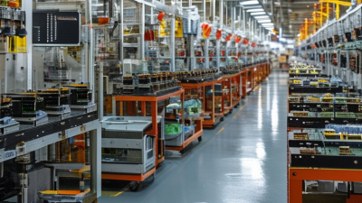
The top 10 pick and place PCB machines in 2026 are best compared by the work they can sustain, not headline speed alone. A compact benchtop unit may suit prototypes and short runs, where quick feeder changes matter more than maximum throughput. Mid-range platforms typically balance placement speed, board size, and setup flexibility for growing production. High-volume lines need fast component handling, dependable vision correction, and smooth integration with printers and reflow ovens.

Look closely at rated placements per hour, but ask how that figure was measured. A board with tiny passive components may run very differently from one carrying fine-pitch integrated circuits. Check feeder capacity, supported component sizes, nozzle changes, and the time needed to switch jobs. These details affect daily output. So does software.

For a small workshop, a simpler machine can reduce training and maintenance demands. A contract manufacturer may value dual-lane operation, traceability, and repeatable changeovers instead. Request a demonstration using representative boards, then compare actual placement results and changeover time. A quoted speed can flatter a machine; real production includes pauses, replenishment, and inspection. No ranking fits every buyer. Even careful comparisons leave uncertainty until the machine meets your boards, operators, and schedule.

How to Choose a Machine for Your Budget and Workflow

For a 2026 pick-and-place purchase, start with the boards you actually build—not the machine’s headline placement speed. The International Federation of Robotics’ World Robotics 2024 report recorded 4,281,585 industrial robots operating worldwide in 2023 and 541,302 installations that year. That signals wider automation investment, but it does not prove every PCB line needs maximum speed. A small-batch workshop may gain more from quick feeder changes and simple programming than from a high-speed platform.

Match the machine to component range, board dimensions, expected volume, and operator skill. Ask suppliers to demonstrate your own board mix, including fine-pitch parts and awkward connectors. Compare verified placements per hour, changeover time, feeder capacity, placement accuracy, and service costs. Rated speed can look impressive. Your real bottleneck may be solder paste printing or reflow, not placement.

Budget for more than the purchase price: feeders, nozzles, software, training, maintenance, and floor space all affect ownership cost. A practical trial should measure usable output across a normal shift, not just a short test run. One trade-off is easy to miss: flexibility can cost throughput. It is worth questioning whether frequent product changes justify that expense. Some buyers may still choose a faster machine than their workflow needs. That happens.